Mapping solid polyhedra to tensegrity structures
Read here about a proposal by Lutz Golbs to assign names of solid bodies from classical geometry to tensegrity structures.
Introduction
Many (man-made) tensegrity structures correlate to the shape of 'solid' bodies described originally in Greek geometry. Lutz Golbs suggests here a mapping of well-known names for this shapes to Class 1 tensegrity structures. This kind of mapping might make it easier to transfer knowledge about the behaviour and properties of certain structures to physical models.
Skelton and Oliveira proposed a wider definition of tensegrity systems, which distinguishes different classes of these structures:
"A tensegrity configuration that has no contacts between its rigid bodies is a class 1 tensegrity system, and a tensegrity system with as many as k rigid bodies in contact is a class k tensegrity system."
Regular polyhedral structures can be described by the number of vertices, edges and faces and their relation to each other. In idealised form, they are often represented by wireframe drawings, showing all edges (and therefore, showing the vertices as well, yet leaving the faces transparent). In the physical universe, the objects deviate from this idealised description. A dice has a cubical shape, although most of them have rounded corners, so technically they represent a stellated (truncated) cube. It still makes sense to 'ignore' the stellation while considering the overall behaviour of the dice, the 'cube-ness' supersedes the 'stellated-ness'.
By considering the rounded corner of a dice as the vertex of an 'ideal' cube we intellectually 'zoomed out' of the object, by making the measurement more coarse the complex shape of the rounded corner transforms for practical purposes into a vertex where equally long edges meet in the 'same' point in space.
Deriving a construction plan from a geometric shape
Lutz Golbs found so far two methods to 'tensegrify' regular, symmetrical polyhedra. One seems universally applicable, the other works only for the icosahedron (v=12, e=30, f=20) and the dodecahedron (v=20, e=30, f=12).
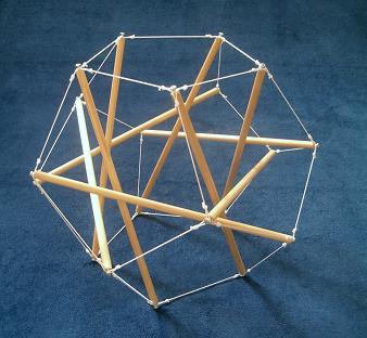
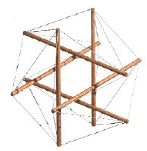
Method 1: Connecting non-adjacent vertices with struts. This method requires v/2 struts, ie 6 for the icosahedron and 10 for the dodecahedron. The tendons of a 10-strut dodecahedron share the topology of the edges of the Platonic Solid with the same name, while a tensegrity icosahedron lacks 6 edges, so that 12 trigonal faces merge into 6 rhombic faces. All vertices in a tetrahedron are adjacent to each other, which prevents building a 4-strut class 1 tensegrity.
Method 2: Converting edges into struts. This method worked with any regular shape so far, and means to stellate all corners. The tendon then outline a stellated version of the Platonic Solid. All Platonic Solids can be build with the method. Like the rounded corner in a dice, the vertices lose their 'idealised' state and transform into a tension loop. The struts rotate around the imaginery vertex in either clockwise or counter-clockwise direction. Each strut has exactly three tendons on each end, two of which connect to the vertex loop, and one to another vertex loop. The connections from loop to loop have the same topology as the original Platonic Solid.
||~ Platonic Solid ||~ faces ||~ edges ||~ vertices ||~ Edge per vertex ||~ Struts ||~ 'Loop' tendons ||~ 'Edge' tendons ||~ Minimal tendons || || Tetrahedron || 4 || 6 || 4 || 3 || 6 || 4x3=12 || 6 || 18 || || Cube || 6 || 12 || 8 || 3 || 12 || 8x3=24 || 12 || 36 || || Octahedron || 8 || 12 || 6 || 4 || 12 || 6x4=24 || 12 || 36 || || Dodecahedron || 12 || 30 || 20 || 3 || 30 || 20x3=60 || 30 || 90 || || Icosahedron || 20 || 30 || 12 || 5 || 30 || 12x5=60 || 30 || 90 ||
Cube and octahedron are 'duals', as are dodecahedron and icosahedron, ie the vertices of one shape correlate the faces of the other. Tetrahedron, cube and dodecahedron have triangular corner loops, octahedra square loops, and icosahedra pentagonal corner loops. The stellation changes the original shape of each face as well, triangular faces become hexagonal, squared faces octagonal, pentagonal faces become decagonal. The graph consisting of the network of tendons has then one additional face for each vertex of the Platonic Solid. That means duals will have the same number of struts, tendons and faces on the graph derived from the tension network.
The number of edges connecting to a vertex distinguishes duals, and the shape of faces distinguishes physical models of these special set of tensegrities. A 12-structure with 6 square faces (plus 8 hexagonal) is therefore a (stellated) octahedron, a structure with the same number of tendons and strut yet 8 triangular face (plus 6 octagonal) represents a cube.
The method to convert edges into struts works for non-Platonic Solids as well, eg Cuboctahedron, rhombic dodecahedron and prismatic shapes. Maximal symmetry requires that the struts cross each other in each corner in the same direction (chirality). Structures with mixed chirality behave much less symmetric and balance less stable.
I suggest considering tensegrity systems build with above method which show the same chirality along its faces as Atomic tensegrity representation of the Platonic Solids or shorter, Tensegrity Atoms. Obliviously, and similar to modern physics, these atoms are made of small units. Accordingly, the minimal tensegrity structure with 3 struts and 9 tendons can be described as tensegrity electron, which can be positively or negatively charged, depending on the spin. The chirality of a structure means that two physical structures represent each Platonic Solid (and the tensegrity electron).
Besides introducing the ideas of tensegrity atoms and tensegrity electrons, and following their mapping to the Platonic Solids, Lutz Golbs suggests neglecting the constructive necessity to truncate corners, and follow basically the established naming for untruncated solids. Objects constructed by converting edges into struts all fit into this scheme, complex objects can be either described by identifying its module, or still be named along the imagination of the builder.
Links and References
Lutz Golbs: website; he is also a user of the Alexander Technique Wiki. Martin Friedrich Eichenauer and Daniel Lordick: [1]

